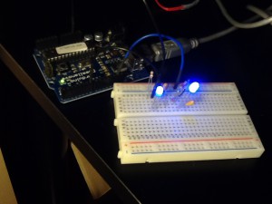
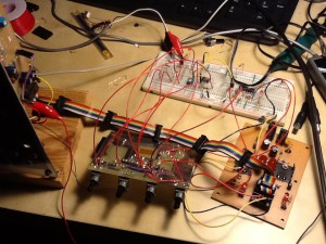
Right: charged, left: normal 5V drive
A charge pump is a circuit that boosts DC voltage. I tried to make a charge pump using Arduino to enhance power supply for a blue LED. A blue LED typically has higher forward voltage. Some ones go to 4V, so 5V-supply processors are slightly powerless to drive it. Thus a charge pump helps to enhance blue LED brightness.
As you can see in the photo above, charged one is brighter. The supply voltage was increased to 8V in this case.
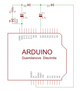
Here is the schematic:
The sketch is pretty simple :-)
void setup()
{
  pinMode(7, OUTPUT);
}

void loop()
{
  digitalWrite(7, LOW);
  delayMicroseconds(100);
  digitalWrite(7, HIGH);
  delayMicroseconds(100);
}
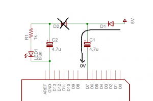
How it works:
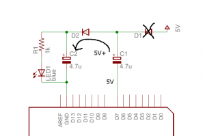 step2: move the charge in C1 to C2.
This is a useful circuit when you want to enhance voltage to a load quickly.
Enjoy!




Hallo Gaje san,
You have used 4.7uF capacitors and a cycle time of 200microseconds.
How do you calculate the output voltage vs these two parameters.
Bas Kasteel
Hi Bas,
I determined capacities and cycle time by try and error. Higher frequency and larger capacitors were better. There could have been even better parameters, but I didn’t tried further.
Theoretical limitation of output voltage is around 9V. You would see this voltage when we remove the load (i.e., LED).
Calculation is Vout = 2 * Vcc – 2 * Vf
where Vcc is supply voltage (is 5V for Arduino), Vf is diodes’ forward voltage (is about 0.5V typically).
When the circuit has load, the output goes slightly lower. Higher frequency and larger capacitor pushes up the output but it never goes beyond the theoretical limitation.
If you are familiar with LTSpice, you might find this simulation interesting:
http://gaje.jp/resources/ChargePump.asc
This gives view of how charge pump works.
V1 in this model is what Arduino is doing.
I am very intrigued by your ADSR based on avr. I started to develop a adrs with ATtiny1634. In the past I made this: http://digilander.libero.it/ismsynth/vc-adsr-1.2.jpg … which works fine but the BJT must be matched. Mind that the ADSR volatge inputs are designed to be driven by an operational amplifier that serves as a S/H, if you connect directly a potentiometer is better to interpose a opamp buffer. Regards
Hi Massimo,
Happy to know you also started the project with AVR EG. Your analog VCEG is also interesting. I also tried the analog approach first but I eventually decided to implement it by a micro processor, since I want to add more features that are hard to achieve by analog approach, such as time scaling by note.
Anyway good luck with your project!
Hi, I really appreciate that you explained the individual steps. It helped clarify the situation for me, a mech student playing with mcus :).
I was wondering one thing, though. Elsewhere I have seen people add a component to measure the output voltage and increase frequency of charging only if needed. I believe they said they do so to save energy because running the charge pump is wasteful if the output doesn’t need charging. However, with your setup it is unclear to me that running the pump at higher frequency (say, with a PWM output) would be particularly wasteful. If the 2nd cap is already at full charge…then not much energy will be used.
Am I missing a key detail?
Hi Tomek,
Higher frequency makes behavior more stable in general. Short charging/discharging time makes smaller voltage flatter in output. You can easily experiment different frequency by changing delayMicrosecond times in the source code.
But, this circhit may be too hacky for measuring efficiency. You usually use much better switch and capacitor for efficient pumping.
I am no longer sure the place you’re getting your info, but great topic. I needs to spend a while studying much more or understanding more. Thanks for wonderful info I was on the lookout for this info for my mission. ebdgkckdeagb