–> Japanese version of this article
1. Introduction
Optigan is an optical organ manufactured in 1970’s as an easy-to-play instrument by Matel, a U.S.A. based toy company.
It looks like this:
looks good. How about sound?
Wow, I like the sound a lot.
However, it’s been long since the Optigan is terminated. It is quite difficult to obtain the organs in Japan. I kept studied on this organ, then I knew there was an improved version of optical organ, Orchestron. But it is more difficult to obtain, nearly impossible.
But, I happened to know the discs for Optigan and Orchestron are still available. OK I’d get them. How do I do with the player? Hmm… OK I’d make it.
I started this project like this: Making an optical organ.
2. The Optical Discs
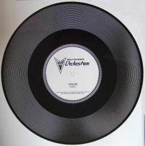
First thing I did after I received the discs was investigating. First of all, the appearances are as follows. The left side is for Optigan and the right side is for Orchestron.
The Orchestron disc is thicker than Optigan, and robust against scratches. The Orchestron disc surely looks to be improved version.
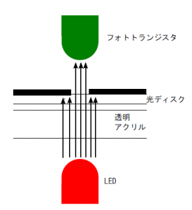
The theory to make the sound from the disc is simple.
Like above, the disc has multiple tracks placed as concentric circles. Each track has a waveform pattern as thickness of light slit. So waveform signal is generated by picking up the light through the slit in the rotating disc.
I tried if you can actually pick up the sound from the disc:
So far so good.
3. Overview of the Design
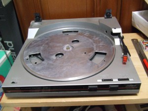
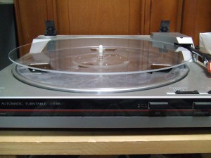
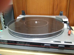
The goal of the project is to read Optigan and Orchestron discs. The hardest part is to make rotating mechanism to turn discs, so I decided to modify an analog record turntable. the project would be much easier by exploiting its rotating mechanism. Luckily, the size of the optical discs are mostly the same with analog LP disc.
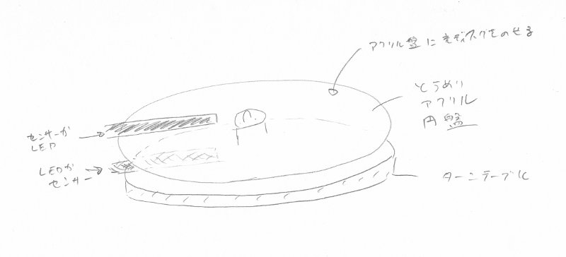
The image of the design is like following:
A clear and round acrylic table is placed a few centimeters above the turntable so that we can put the organ disc on the table and bind it by optical transistor and light source from above and beneath.
4. Measuring the Discs
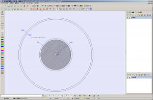
I need to draw a detailed design from the rough sketch above in order to actually make the player. So the first information I need is dimensions of the disc.
I could not find any information about it on the net. But no problem, I have the actual discs so I can measure them. Accurate pictures of the discs follow. The left is Optigan and the right is Orchestron.
The Optigan disc has 58 tracks. The Orchestron has 37. Both discs have 1.397mm/0.055inch track pitch.
Positions of Optigan and Orchestron tracks are the same (Orchestron is subset of Optigan).
So you may make the Optigan and Orchestron player without replacing the disc reader.
5. Player Design
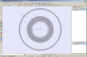
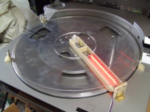
Now I know the disc dimensions so next thing to do is mechanism design. I designed the mechanism as an attachment of record player. The final design is as follows:
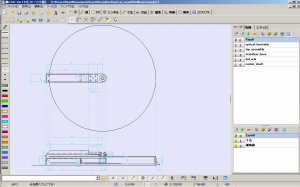
Following the initial idea, I placed a clear disc 20mm above the turntable with two arms stretched above and below the disc. Above has optical optical transistors for each disc tracks. Below has LED light source.
6. Making the Disc Assembly
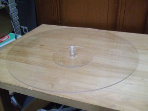
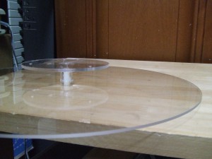
Design has been done. Now it’s time to making parts. The first one is the clear disc assembly. This is an H-shaped object like a huge bobbin.
this is made of parts like these:
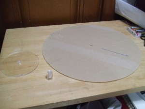
I used a CNC milling machine to make the left small disc. The large right disc is a ready-made one bought from a plastics shop. The part in center is made from acrylic pipes and an ABS bar.
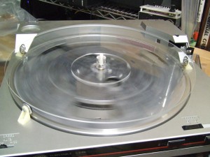
This part is done by placing on the turntable. However, I found the disc flatters when I rotates the disc. Moreover, this is a plastic plate so it might be bent over ages. So I added three toy wheels as stabilizers.
Now it looks fine.
At this point I verified if I can go with this design. OK good to go.
7. Making the LED light arm
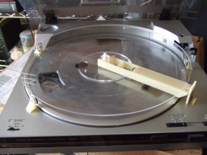
The design of the LED arm is as following
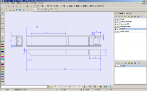
On the left hand I will have a supporting wall where I attach the arm using a hinge. On the right side the arm lightly bites the shaft of the clear disc assembly. Also I need some mechanism to keep the arm floated. So I used a toy wheel again.
Done with the LED arm. Looks good.
By the way, I used ABS as the material of mechanical parts except clear ones. For clear parts, I used acrylics. I used a CNC milling machine to cut the materials out.
8. Making the Sensor Arm
Two arms are needed for the optical organ. One was the LED arm for light source. This is placed under the clear disc. On the above is the sensor arm. The arm visible from above in the overall design picture is the one. One side is attached to the supporting wall using a hinge. The other side is put on the center of the disc. I have a ball bearing there to prevent friction against the disc.
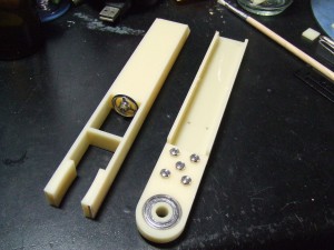
Cut and assembled arms:
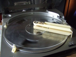
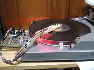
And placed them to the disc.
9. Making the LED Array
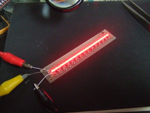
The mechanism is mostly done. Next I need to make electrical parts. I started with the LED array. This is the light source for the optical sensors.
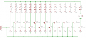
The schematics is below. The LED drivers are constant current circuit using transistors. The currents are controllable by the base voltages in the transistors.
10. Making the Sensor Array
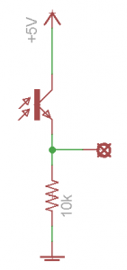
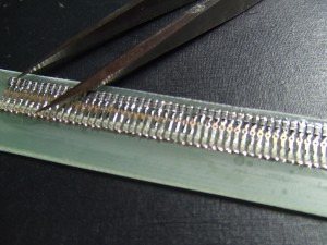
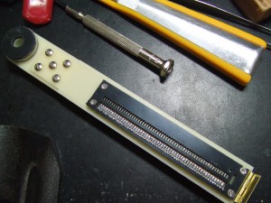
The schematics of the block per single track is as follows. The sensor array has 58 blocks.
The soldering was a bit hard.
11. Making a Screen
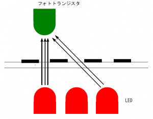
One of the major problems in making optical organs is crosstalk. The original Optigan and Orchestron had the same problem. So the Orchestron, the improved version, has 5th interval progression in their tracks to make crosstalk less noticeable while the Optigan is chromatic.
What is crosstalk? The following picture explains well.
So the crosstalk is a problem that a photo transistor picks up signal from next track. The organ in this project has the issue as well.
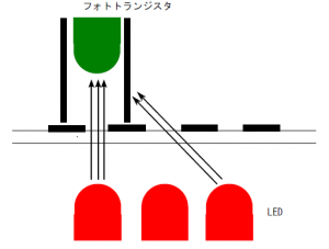
What is the solution? The following picture explains well.
So you can prevent crosstalk by placing screens.
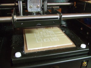
I made the screens as following. The black plate has the screens. Each fine hole along the center axis has photo transistor in it. The walls of the holes work as screens.
This was a challenge against the limitation of the milling machine (well, it’s for me. maybe other people are better :-).
12. Making the Control/Mixer Board
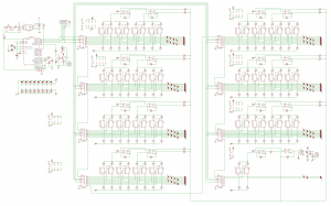
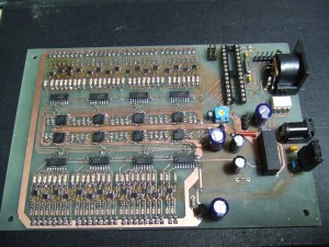
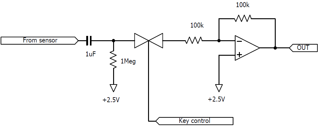
An Optigan disc has 58 tracks. The player reads these 58 tracks simultaneously. In order to play the disc, you need to choose tracks you want. In other words, you need a switch for each track. The control/mixer board does the work. This board chooses the tracks the performer want and mixes the signals to output. The schematic is as following. It’s simple but quite large-scale.
The board receives signals from the sensors through capacitors. And they go into mixers. Between those, each signal is controlled by a C-MOS analog switch. The analog switches are controlled by ATMega88 micro processor via shift registers for switch signal serialization. The order from the performer is received via MIDI. The micro processor also decodes the MIDI signal.
Following is the finished control/mixer board.
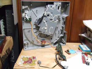
13. Modifying the Turntable
I did not plan to modify the base turntable so much, but I had to remove the cartridge arm that disturbed the sensor arm assembly. This removal requires another removal, and so on, I had to almost all mechanism to drive the cartridge arm.
Also I added a tuning dial that changes the rotation speed.
14. Connecting the Arms and the Board
Next I connected LED/sensor arms and the board each other. There was no difficulty at this part. It was sodering, soldering, and soldering.
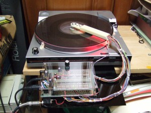
15. Making the Frame
The frame is not luxury. It is just made of an acrylic plate on the board on an acrylic base. But I am happy with the player hardware done.
16. Programming
The last but not least is programming. The controlling board has a micro processor that decodes MIDI signal into ON/OFF order to the switches.
Mappings between MIDI notes and the optical tracks are different between Optigan and Orchestron. So I made two types of mapping tables and invokes them according to the MIDI channel. The processor uses the Orchestron map when it receives channel 1 MIDI. If it is channel 2 MIDI, the processor uses the Optigan map.
17. OK, It’s Time to Play
Also, I made a song for the optical organ:
18. What’s next?
I want to play this organ for a while. Meanwhile, I might have some idea for improvement or some gimmicks. In some future, I’d make the another version. Currently, following ideas are on the list.
- Use a DJ turn table. That has much more strong torque that makes operations easier.
- Make it scratcheable.
- Make it as an attachment to a record player, rather than modification.
- How about making the light source full color?
- How about extending note ranges by using some signal processing?
Also, it is nice if I can make the optical disc by myself. That makes the usages of the organ more wide.
Thank you



Pingback: Tweets that mention Optical Organ | gaje -- Topsy.com
Can you get rid of the clicks by wiring in capacitors?
Thank you for the comment. Actually I already have capacitors wiring in. Yes the clicks are somewhat annoying. I have not investigated the cause yet but I suspect it is due to weak power supply.
Hi,
I just see your optigan orchestron diy project ,this is simply awesome!
I dream that somebody makes a portable optigan and you make it :-))
In the future,is it possible to buy from you a DIY portable optigan,I would be the most happy man in the world?
Thanks for all
Jean(belgium)
Pingback: Resurrecting the Optigan disc format - Hack a Day
Pingback: Resurrecting the Optigan disc format | You've been blogged!
You might try a PWM drive to the TT motor. I’m not sure that it would be responsive enough to provide note bends in real time, but I thought you might come up with some effects of your own using it to simulate ADSR functions. Who knows? You do great work, and you’re obviously quite patient (judging by all that fine surface mount soldering in this project)… Oh yeah- kudos for re-engaging an obsolete technology in my very favorite field- electronic MUSIC!
You can get rid of the clicks by setting up the switches such that they only turn on or off at a zero crossing of the waveform.
Hi! Found your project via Hack-a-Day. Nice job! Actually, I had something very similar in mind a while ago – an optical tonewheel/drawbar organ. It never really materialized, though seeing your project, I think it won’t be long before I’m sitting on it again ;-) Is there any reason you’re using static illumination and doing the mixing on the receiver side? It would seem that the opposite should require a lot less hardware: modulate the LEDs and just add up all the detector signals.
Cheers, Matthias
Pingback: Resurrecting the Optigan disc format | House of Mods
Wow, this is amazing! As an Optigan owner/sufferer, I find this very intriguing. An actual Optigan is as much of a force of nature as it is an instrument: less-than-responsive key/button contacts, the constant drifting of speed, and the general “Rube Goldberg” nature of the device. Something like this might be a way to keep the concept of the Optigan/Orchestron going after the organs themselves have stopped working, while sounding more “real” than a set of samples.
As an aside, did you know why the key layout for the Optigan and Orchestron are different? For the sake of improved sound quality, the designers of the Orchestron shifted the note tracks towards the outer edge of the discs, where the accompaniment chords would normally be on an Optigan disc. Therefore, using an Orchestron disc in an Optigan would result in the notes being distributed across the chord keys and the bottom of the keyboard, while the reverse would result in several of the chord sounds being distributed around the keyboard. Anyway, I wish you the best of luck with your endeavor!
-Adam
Pingback: Resurrecting the Optigan disc format « Black Hat Security
I have done some research on the disks and the audio and the creation process. There is no way to get rid of the pops. The pops are on the disks themselves. The disks are a special film that was made by Kodak for the Optigan company. There was no way to create a even loop in the audio, therefore there is a small pop when the loop starts over. the recreation disks at optigan.com overcome this because of new techniques they guys over there used.
Super cool project, I am in awe of your engineering and manufacturing skills, not to mention your soldering abilities. I love the idea of a scratchable player! Just curious, what sort of process would you use to actually create an optical disc?
Thank you for so many comments, and sorry for my reply being very late.
Hi Jean,
> In the future,is it possible to buy from you a DIY portable optigan,I would be the most happy man in the world?
I’m trying to making this releasable, but it will take long. I have a lot of challenges to doing this.
Hi obsoe hollerith,
Yes some functionality to control amplitude linearly should be useful, not only for avoiding the pop noise but also for enriching the sound. I’m looking for practical way to do it. Yes PWM would be a strong candidate.
Hi Jas,
It’s an interesting idea. This requires A/D converting but it’s still interesting because importing the sound in digital domain might bring some other enhancement.
Hi Matthias,
> Is there any reason you’re using static illumination and doing the mixing on the receiver side? It would seem that the opposite should require a lot less hardware: modulate the LEDs and just add up all the detector signals.
I agree. Actually I’m also seeing the approach you’ve suggested. Following are the reasons to separate signals at the receivers in the first trial:
– First of all, I’m following the original design. Optigan is doing the same way.
– I would like to process picked up sound, such as applying ADSR, analog filter, etc. In that case, the signals are easier to handle if we get them as a single tone per channel.
Hi Dr. Optigan,
> As an aside, did you know why the key layout for the Optigan and Orchestron are different?
I think it’s for reducing bad effect from cross-talking. In Optigan, tracks are chromatically increasing. It’s simple and easy to understand but cross-talk is quite noticeable since the sound would be dirty when it happens. In Orchestron, next track has 4th or 5th interval so cross-talk is less annoying.
Hi Impulse405,
Thanks for the comment. I’ve heard that optigan.com people have successfully eliminated the pop sound due to the track connection that must happen once per round. I’m using ones from the optigan.com. So I also do not have this type of pop noise. Mine is something coming from my electric circuitry. I guess it’s switching noise from logic gates that are used for driving analog switches but I’ve not closely investigated it yet.
Hi Will,
Currently I’m buying discs but I’m also planning to make my own. Some prototyping has been done. I’m drawing track patterns from waveform arrays (such as .wav file) to PDF file so that I can print them out onto clear sheets. I thinkI cannot make large discs such as ones optigan.com provides but half-size like 15cm diameter would be possible.
I met you at a synth meet in Berkeley (at gilman) and I got a chance to play around with this thing. I immediately fell in love. I didn’t know it was based off an optigan, or know what an optigan is until now. I just read an article about optigans and realized that it was just like that awesome thing I saw at the Berkeley synth meet! Since I’ve been wanting one of these for a long time, I’m looking to buy one. I saw one for $600. But I’d much rather have your device. Is there any chance that you could build me one pretty please :-) I am willing to pay more than the $600 price that was quoted for a fully restored working optigan. If you are willing to build one just name a price that you think is fair.
Anyway shoot me an email when you get a chance. If you don’t have the time to build one let me know so I can jump on that optigan for sale :-)
Thanks, and I hope we meet again perhaps at another synth meet so I can play your optigan again!
hey i found a few of these discs….
its people like you my friend who make humanity worth fighting for. Sometimes i lose hope and then I find stuff like this. Awesome. Plus you uploaded on my birthday!
awesome..
what happens if you blow some fog or smoke between the disc and the reader ? does this thing then start to do italo ?
Hi Gan,
I’m the guy that makes the Optigan and Orchestron discs for Pea Hicks at Optigan.com.
I’ve been working on a portable Optigan/Orchestron disc player for a few years now. Email me back if you’d like to discuss this.
Best Regards,
-Robert-
Hi Gan,
I’m studying Design Products on RCA in London.
I’m making a project about optical sound technology. Can you give me an advice what kind of optical transistor is the best for this purpose? And how plug it to the amplifier. I’ll be very thankful.
Cheers
Jan
Hi Jan,
I used photo transistors SFH 3010 which are available from Digi-Key. I chose them rather because of their size than sound quality. Optigan disc has only 1.4 mm / 0.055 inch of track interval. There are not so many types of transistors that fit this size. So I simply used usable and available one. I also felt electric characteristics of the photo transistors is a minor issue than mechanical placement of them. Any photo transistors behave somewhat similarly electrically. But angle of light, relative position of transistors to tracks, etc., affect the sound a lot.
About the amplifier, I just plug the mixer board output into the amplifier. The mixer board output is line level.
Hi Gan,
Thank you for your reply. May I ask you one more think. What kind of phototransistor have you used for the trial pick up? I’ am trying to do something similar with sound on a film tape for my school project, but I still can’t achieve proper effect. Sorry for bothering you.
Best wishes,
Jan
Hello! This project is so cool! Is there any way you could post or send me the schematic for this? I’d love to build one of my own. Please email me if you are willing to share the schematic and partlist!
Hi Spencer, all necessary schematics are on this page. I don’t have the partlist but all part names are on the schematics.
Amazing project! Is it just me, or is the “Missing Link” song inspired by the Tri-Lambs’ performance at the Greek Games in “Revenge of the Nerds”?
I have a non working optigan organ and it’s driving me crazy since only my mother knew how to open the side in orer to get to the player. It’s like a secret compartment which convinces me that the inventor must have been a crackpot. I’d hire a repairman but I doubt most humans would be totally confused by this bizarre machine.
I’ll probably end up selling it and have 10 discs and other materials. If anyone knows how to open the side where the playeri s, please advise. The company Mattel/Fischer Price is playing dumb. Just looking at the darned organ makes me want to scream lol! You did a great job there-I’m not great at working with technical objects.
Hi!
I’m late to the party, but since early 2025 I started designing (DIY printing) my own Optigan discs (+30 designs right now). I was wondering if you could be willing to share knowledge. I really want to build my own Optigan, not an expert in electronic, but good in mechanics.
I could do custom design, or give you all my ”ressources” and tools for making your own disc if you are willing to share your knowledge in the build of the instrument,
Thanks
Xavier
Hi Xavier, sorry to be late for reply.
I’m happy to share. About the knowledge, things written in this page are pretty much I have. But I can also share my resources such as design files of the components and eagle schematic and board files. Email me at naoki dot iwakami at google dot com for contacting me directly.