Posted intech notes
Noise Source Transistors Test
Previously, I’ve picked up several transistors as candidates to be used for noise source for noise generator.
https://gaje.jp/2014/01/14/2915/
I’ve started testing these transistors.

Previously, I’ve picked up several transistors as candidates to be used for noise source for noise generator.
https://gaje.jp/2014/01/14/2915/
I’ve started testing these transistors.
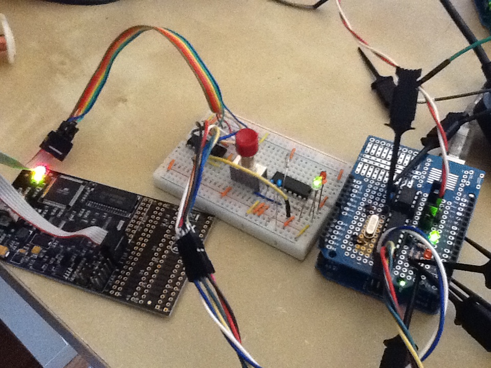
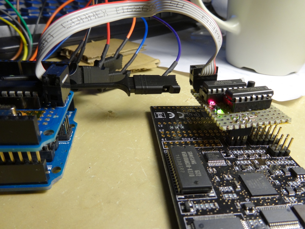 As mentioned in my previous post, AVI Dragon’s SPI pins in debugWire interface have to be disconnected during debug run in order to properly run an application that uses SPI / USI. I also noticed that the Dragon dominates RESET pin, too. In my project, I’m resetting target chip from Arduino. The Dragon is killing this functionality as well. This makes me quite uncomfortable with my development work, so I’ve enhanced the switch I made on bread board previously, and made a helper device. It’s nicely working. I named it “Dragon’s Tail”.
 AVR Dragon provides on-chip debugging feature through debugWire interface. The debugWire utilizes the ISP six-pin header to control the target device as shown in the following link:
http://www.atmel.no/webdoc/avrdragon/avrdragon.section.zrr_osd_lc.html
However, the target application does not work correctly with SPI feature during debug run.
Typical analog noise generators make signal by amplifying AC component coming out from zener current of transistors reversely biased between emitter and base (here’s an example circuit).
Any bipolar transistor would work as such a noise source, but noise quality in listening is different from part numbers. 2SC828A is well known as good noise source, but it’s been obsolete for long. So for Analog2.0, I have been recommending 2SC3311 instead. But this part becomes obsolete as well. Now I have to find another one.
As a part of my current experiment, I’m running following piece of code:
   if (digitalRead(pinDeviceReadReady) == HIGH) {
    Serial.println("DATA READY");
    spiSend(0x20); // command "read request"
    readBuffer.deviceId = spiReceive();
    Serial.println(readBuffer.deviceId);
    readBuffer.wireId = spiReceive();
    Serial.println(readBuffer.wireId);
    readBuffer.length = spiReceive();
    Serial.println(readBuffer.length);
    for (int i = 0; i <= readBuffer.length; ++i) {
       readBuffer.data[i] = spiReceive();
       Serial.println(readBuffer.data[i]);
    }
  }

where

inline void spiSend(uint8_t data)
{
  // wait for device ready to write
  while (digitalRead(pinDeviceWriteReady) == LOW);
  SPI.transfer(data);
}

inline uint8_t spiReceive()
{
  while (digitalRead(pinDeviceReadReady) == LOW);
  uint8_t data = SPI.transfer(0);
  return data;
}
Continued from this article. I’ve done with the phase one experiment.
The goal of phase one experiment is to implement end-to-end application with minimum struggle for hardware design and implementation.
I am sure there will be a lot of testing work before I put the communication device in real applications. So I first want a tool to test the driver and protocol. Thus, the application for the first phase is a protocol tester that provides command line interface and several diagnostic commands / functions.