Inter Module Communication

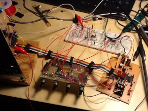
I’m going to try making a digital communication bus for synthesizer modules.

Analog synth has a very simple control language which is voltage.  Any message is translated to voltage that can be read by any modules that accept voltage input. So for example, VCO output is basically audio output but also can be used as control voltage of some other modules, such as VCO cross modulation.

This simple data exchange methodology makes analog synthesizer very versatile and flexible.  However, as a drawback, patch wiring would become too complicated as you make complex module network.

One solution for making the wiring simple is to use a single common data bass where all modules are connected, and exchange data selectively using some software.  Apparently, making such a bass for analog signals is impossible or extremely difficult. So I’m going to try making it using a digital bass.

Basic Study of Voltage Controlled Envelope Generator – Full Calculation Approach

I did basic study of voltage controlled envelope generator based on analog circuit approach.  However, I found the implementation quite complex, although its quality was good.  So, I next tried another approach that has simpler circuit.  This version calculates the EG curve using micro processor, and makes analog output using PWM with minimum external filtering circuit.

This version is inspired by Tom Wiltshire‘s Voltage Controlled ADSR Envelope Generator.


Basic Study of Voltage Controlled Envelope Generator – Analog Approach

I’ve started studying voltage controlled envelope generator designs, since I have several use cases of it.

An envelope generator usually is implemented by an RC charging circuit with potentiometers as resistors.  However, such design does not capable of quick parameters change.  So voltage control (or digital control) functionality is necessary for better articulation.  Also, non-potentiometer control is crucial to polyphonic voices.

There are several approaches to design voltage controlled envelope generators.  This article describes about an analog approach which I tried first.

Matching Transistors, 2SC1815 or 2N3904

You need to use well matching transistor pairs to make a good quality transistor ladder VCF. Above is the classic methodology to find matching transistor pairs.  I tried this procedure with 2SC1815 and 2N3904 I have.  Next version of Analog2.0 boards will support the both types of transistors, so I wanted to know how different they are in VCF perspective. Here is the result: The result shows that 2N3904 has less variability. This comparison might not be fair since my 2SC1815 transistors are very cheap ones purchased from Akizuki-Denshi, so these might have different quality control in manufacturing than usual retail transistors.  But at least I learned following: 2N3904 is…

How to Convert Sampling Rate with Java

This worked for me. http://stackoverflow.com/questions/2276027/converting-the-sample-rate-on-the-fly-when-reading-a-wav-file-into-a-samples-arr You can convert by applying AudioSystem.getAudioInputStream to an AudioInputStream object, and you get another AudioInputStream as the result.  Here is the sample code of the part: AudioInputStream inStream = AudioSystem.getAudioInputStream(soundFile); AudioFormat outDataFormat = new AudioFormat(8000.0f, 16, 1, 2, true, false); AudioInputStream outStream = AudioSystem.getAudioInputStream(outDataFormat, inStream); In order to make above code work, we need following two extensions.  Without these extensions, we get exception on the execution above. http://www.tritonus.org/tritonus_share-0.3.6.jar http://www.tritonus.org/tritonus_remaining-0.3.6.jar

More on Semiconductor Switch

Continued from yesterday’s article.  Here are the switches I compared.

Mechanical Push Switch (Tactile)

You hear click noises.
[audio:https://gaje.jp/blog/wp-content/uploads/2011/12/tactile.mp3|titles=tactile]

Relay

There are occasional pop noises.
[audio:https://gaje.jp/blog/wp-content/uploads/2011/12/relay.mp3|titles=relay]

Analog Switch

Not bad but click noise intermittently happens.
[audio:https://gaje.jp/blog/wp-content/uploads/2011/12/tactile.mp3|titles=analog_sw_chat_cancel]


JFET Switch

 The most stable so far.
[audio:https://gaje.jp/blog/wp-content/uploads/2011/12/JFET.mp3|titles=JFET]

Charge Pump with Arduino

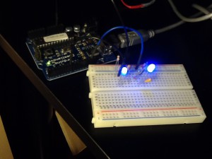
Right: charged, left: normal 5V drive

A charge pump is a circuit that boosts DC voltage.  I tried to make a charge pump using Arduino to enhance power supply for a blue LED.  A blue LED typically has higher forward voltage.  Some ones go to 4V, so 5V-supply processors are slightly powerless to drive it.  Thus a charge pump helps to enhance blue LED brightness.

As you can see in the photo above, charged one is brighter.  The supply voltage was increased to 8V in this case.