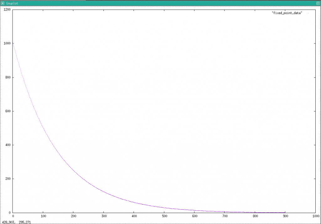
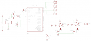
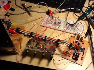
In the previous article, I considered how to calculate a decay curve without using a lookup table. I tried implementing it to a microprocessor (atmega168). But I hit a few obstacles.
First I planned to keep envelope value as a Q10.6 fixed point number (meaning 10 integer bits and 6 fractional bits), so that I can conveniently use a 16-bit integer. But I found it does not give enough resolution of the data. I needed to extend it to 32-bit (Q10.22). Integer part is enough with 10 bit because it’s the resolution of the PWM output.
Then I wrote a program like following (shortened from the actual program). It looks to work, but it did not. The value did not show up to g_value where I keep the current envelope amount.
olatile uint32_t g_value;  // value holder, Q10.22 fixed point number
volatile uint32_t g_decay_factor;  // amount of decay,  Q0.32 fixed point
volatile uint8_t g_update_ready;

ISR(Time1_OVF_vect) {
  OCR1A = g_value >> 22;  // reflect the value to PWM、Q10.22 to integer
  g_update_ready = 1;
}

void UpdateValue() {
  if (!update_ready) {
    return;
  }
  // reduce the value by multiplying the decay factor
  uint64_t temp = g_value;
  temp *= g_decay_factor;
  g_value = temp >> 32;
  g_update_ready = false;
}

int main() {
  g_value = 1023 << 22; // integer to Q10.22
  g_decay_factor = 0.99309249543703590153321021688807 * 0x100000000;
  g_update_ready = 0;

  while (true) {
    UpdateValue();
  }
}I couldn't find any document or article explaining this, but it seems that avr-gcc, the compiler for AVR, is not following C language standard strictly. I presume it's because there is some necessity to control register usage tightly by way of writing code (but I don't know whether I'm right. I, again, couldn't find any doc yet). I modified the code as follows, then it started working.
volatile uint32_t g_value;  // value holder, Q10.22 fixed point number
volatile uint32_t g_decay_factor;  // amount of decay,  Q0.32 fixed point
volatile uint8_t g_update_ready;

ISR(Time1_OVF_vect) {
  register uint32_t temp = g_value;  // copy the Q10.22 value to a variable
  temp >>= 22;  // Q10.22 to integer
  OCR1A = temp;  // reflect the value to PWM
  g_update_ready = 1;
}

void UpdateValue() {
  if (!update_ready) {
    return;
  }
  register uint64_t temp = g_value;
  // copy the Q10.22 value to a 64-bit int
  temp *= g_decay_factor;
  // multiply by the Q0.32 decay factor
  temp >>= 32;  // shift 32 bit to adjust scale, now it's Q10.22 again
  g_value = temp;
  // copy back to the value holder
  g_update_ready = false;
}

int main() {
  register uint32_t temp = 1023 << 22;   // this is calculated by the compiler
  g_value = temp;
  g_decay_factor = 0.99309249543703590153321021688807 * 0x100000000;
  g_update_ready = 0;

  while (true) {
    UpdateValue();
  }
}The program works even without the “register” keywords. The compiler seems to take care of it.
The key points in the second implementation are:
- Clarify where to load the data (such as g_value to temp)
- Clarify where a calculation happens (use compound assignment operators such as *=, <<=, and >>=, rather than binary operators (*, <<, >>, etc.)
- Do not mix assignment (loading data) and calculation (modifying the data on the register) in a single line
I have no idea which point was effective. But I keep this note hoping it helps when I have similar issue with microprocessor programming in future.


