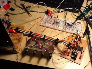
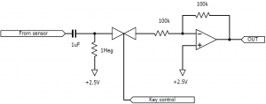
I did basic study of voltage controlled envelope generator based on analog circuit approach. However, I found the implementation quite complex, although its quality was good. So, I next tried another approach that has simpler circuit. This version calculates the EG curve using micro processor, and makes analog output using PWM with minimum external filtering circuit.
This version is inspired by Tom Wiltshire‘s Voltage Controlled ADSR Envelope Generator.
Circuit
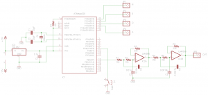
AVR ATMega328 micro processor is used. The circuit has low pass filter to remove high-frequency factor of PWM signal. In order to simulate gate signal, a tactile switch is attached to the PD4 port. The signal offsets from H to L on pressing the switch. There are four voltage inputs that represent attack time, decay time, sustain level, and release time. These voltages are read by ADC pins of the micro processor.
In retrospect, ATMega328 might have over quality. The program size is around 3KB so far and there are many unused pins, so ATTiny44 might be a better choice regarding cost effectiveness.
Program
The program is written in C. Envelope generator curve is calculated from a lookup table that simulates decreasing exponential curve with 256 16-bit values.
Phase and frequency correct 10-bit PWM is used for generating analog output. I’ve tried all types of PWM that AVR supports, that are fast PWM, phase correct PWM, and phase and frequency correct PWM. Then I chose one that gave the best sound quality. PWM threshold that determines output level is updated by every PWM cycle, triggered by the Timer overflow interrupt handler.
ADC is invoked every 10msec approximately. Since the micro processor is only capable of reading one ADC pin at a time, we switch over ADC pins on finishing every ADC read.
As mentioned in the previous study, it should be user friendly to map A, D, and R voltages to transient times exponentially. So I reused the exponential table also for voltage to phase speed mapping.
Unlike typical envelope generators, this EG is triggered at offset of the input (i.e., on pressing the SW), and released at onset. This can be easily reversed by changing the source code.
Behavior
The curve is smooth enough. I did not hear any discontiguous characteristics that digitally-generated sound often has. Actually, I first implemented the curve calculator using 8-bit values table, and I heard the sound flattering during decay. So I’ve increased value precision to 16-bit. Then the flattering disappeared.
Since the circuit is very simple and quality is good, and also since it is easier to add level and time scaling features, this is stronger candidate for my next synth build.


The usage of the atmega328 is very interesting, since i am looking for a envelope generator that offers interfacing over a processor bus. There are enough pins left for 3-4 address lines and 8 data lines. The PIC-controller you evolved this design upon was not versatile enough for my needs. 4bits of address space will offer up to 16 8bit registers to control the envelope.