
The schematic above represents the latest Analog2.0 LFO circuit. This circuit has a long-existing problem. The oscillation affects the power supply and that causes instability in VCO pitch; You would hear the VCO pitch shifting along with the LFO’s oscillation. I’ve tried eliminating this problem.
I suspected the load of rectangular wave output is too heavy. The output of op amp unit IC2B swings from bottom to ceiling of power supply, thus the current that flows in R18 and R19 would be
12 V / (2.7 kOhm + 2.2 kOhm) = 2.5 mA
The current directions reverses when the output switches. Then the output current changes by 5mA. This amount of current change may impact power supply.
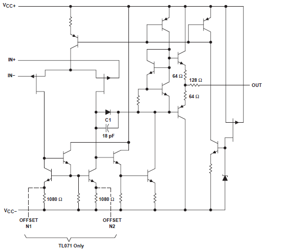
I also checked the schematic of an op-amp unit of TL072 which is used by the LFO. The unit has push-pull output and there is no significant device to limit output current.
In order to reduce the load, I changed the values of R18 and R19 from 2.7k and 2.2k to 5.6k and 4.7k. It worked and the VCO pitch became more stable after the modification.
The change made output impedance larger (from about 1.2 kΩ to 2.5 kΩ). Having an output buffer would prevent impedance change, but I did not go for it. 2.5 kΩ output impedance should be still OK.
